# Flip-flop (electronics)
## Microsim
<iframe src="https://editor.p5js.org/sciencenibber/full/PeZneu3Xn" width="100%" height="620" frameborder="0" sandbox="allow-scripts allow-same-origin"></iframe>
<img src="../SPINTRONICS Images/Flip-flop_(electronics).png" alt="Flip-flop_(electronics) microsim">
*Live sketch: [open in the p5.js editor](https://editor.p5js.org/sciencenibber/sketches/PeZneu3Xn). The poster image above is a placeholder pending an attended or server-side canvas capture.*
### p5.js source
```js
// Flip-flop_(electronics).js -- Wikitube MicroSim
// Hub: SPINTRONICS | Branch: I - Integrated circuits
// Pattern: state machine / clocked bistable (A-V pattern N) + signals-over-time
// timing diagram (A-V pattern H). A flip-flop BLOCK SYMBOL (input pins,
// an edge-triggered CLOCK pin, Q / Q' output LEDs) sits beside the
// selected type's CHARACTERISTIC TABLE, and every CLOCK edge appends a
// cell to a scrolling CLK / input / Q WAVEFORM. The sim is DISCRETE and
// INPUT-DRIVEN -- nothing evolves on its own in time -- so we use
// noLoop() + redraw() on input. That is the safest p5-editor pattern:
// no draw loop for the editor's loop-protector to false-trip, and no
// heavy per-frame inner loops.
//
// CONCEPT
// A flip-flop is a one-bit memory: a circuit with two stable states (Q=0 / Q=1)
// that HOLDS its bit until a clock edge tells it to change. It is the atom of
// sequential logic -- registers, counters, shift registers and the state
// registers of every processor are arrays of flip-flops clocked together. The
// first one was the Eccles-Jordan trigger circuit (1918): two cross-coupled
// inverting amplifiers in a positive-feedback loop, the topology still at the
// heart of every modern flip-flop.
//
// A LATCH is level-sensitive (transparent while enabled); a FLIP-FLOP is
// EDGE-triggered -- it samples its inputs only at the clock transition (rising
// edge ^) and ignores them otherwise. That is what lets thousands of bits
// update in lock-step. Four canonical types, by their next-state (Q+) law:
// SR : Q+ = S + R'*Q (S*R=0; 1,1 forbidden) set / reset
// D : Q+ = D data, delayed one clock the register cell
// JK : Q+ = J*Q' + K'*Q 1,1 -> toggle the universal type
// T : Q+ = T (+) Q T=1 -> toggle the counter cell (/2)
// where ' = NOT, + = OR, * = AND, (+) = XOR.
//
// GOLDEN RULES honoured: one file, one ARTICLE; 720x520 + pixelDensity(2); layout
// derived from width/height (no magic coords in draw); controls carry the
// field's real symbols + meaningful ranges (type index 0..3; S/R/J/K/D/T in
// {0,1}; CLK = one rising edge per press); reset restores ALL state AND clears
// the waveform; HUD watermark (title + URL + hints + live equation) drawn LAST;
// ASCII-only in strings (Unicode only in comments); noLoop()+redraw(); static
// scenery baked into an offscreen buffer so draw() is cheap and loop-free;
// p5.disableFriendlyErrors = true; no top-level name collides with a p5 global
// OR method (checked: none of ratio/split/scale/map/color/red/green/blue/value/
// text/key/select are used as identifiers; no ALT/GRID).
const ARTICLE = "Flip-flop_(electronics)"; // single source of truth (HUD + save name)
// ---- flip-flop catalog -------------------------------------------------------
// name : type label drawn in the body
// in1 / in2 : the pin labels (in2 absent for the single-input D and T)
// two : does this type use a second input?
// expr : ASCII characteristic equation (' = NOT, * = AND, + = OR, (+) = XOR)
// combos : every input combination, in characteristic-table row order
// qn : the SYMBOLIC next state Q+ for each row (Q / Q' / 0 / 1 / X), i.e.
// the textbook characteristic table (general in the present state Q)
const TYPES = [
{ name: "SR", in1: "S", in2: "R", two: true,
expr: "Q+ = S + R'*Q (S*R=0)",
combos: [[0,0],[0,1],[1,0],[1,1]], qn: ["Q","0","1","X"] },
{ name: "D", in1: "D", in2: "", two: false,
expr: "Q+ = D",
combos: [[0],[1]], qn: ["0","1"] },
{ name: "JK", in1: "J", in2: "K", two: true,
expr: "Q+ = J*Q' + K'*Q",
combos: [[0,0],[0,1],[1,0],[1,1]], qn: ["Q","0","1","Q'"] },
{ name: "T", in1: "T", in2: "", two: false,
expr: "Q+ = T (+) Q",
combos: [[0],[1]], qn: ["Q","Q'"] }
];
const MAXCYC = 9; // timing-diagram capacity (cells); bounded ring buffer
// ---- controls ----
let typeSlider, btn1, btn2, clkButton, resetButton;
// ---- state (the source of truth the controls write) ----
let in1 = 0; // primary input bit (S / D / J / T)
let in2 = 0; // second input bit (R / K) -- ignored for D, T
let qState = 0; // the stored bit Q (committed; changes only on a CLK edge)
let waveLog = []; // recorded clock cycles: {a,b,two,before,after,invalid}
let lastType = 0; // detect type changes so we can clear the waveform
// ---- baked static buffer (background, captions, frames, divider) ----
let scenery;
// ---- layout (all derived in setup; never hard-coded inside draw) ----
let divY; // drawing / control divider
let bxL, bxR, byT, byB, bxC, byC; // flip-flop body box + its center
let inLEDx, outLEDx; // input-LED column (left), output-LED column (right)
let ctX0, ctY0, ctX1, ctY1; // characteristic-table box
let stX, stY; // state-readout origin
let tdX0, tdX1, tdTop, tdBot; // timing-diagram trace band
// ---- live pin LED positions (set in draw; read by mousePressed for hit-testing) ----
let p1x, p1y, p2x, p2y, ckx, cky;
let curTwo = true; // does the current type expose a second input?
// ---- palette (ASCII identifiers; none collide with p5 globals/methods) ----
let BG, INK, MUTE, FRAME, BODYC, EDGEC, HI, LO, HILITE, ACC, WARN;
function setup() {
createCanvas(720, 520);
pixelDensity(2);
p5.disableFriendlyErrors = true; // clean + cheap; skip FES overhead
textFont("monospace");
BG = color(14, 18, 32); // deep navy background
INK = color(232, 238, 248); // primary text
MUTE = color(122, 136, 160); // captions / secondary text
FRAME = color(58, 70, 94); // frames, dividers, baselines
BODYC = color(38, 48, 72); // flip-flop body fill
EDGEC = color(150, 165, 195); // body / pin outline
HI = color(60, 214, 130); // logic 1 (green): lit pins, LEDs, traces
LO = color(96, 108, 132); // logic 0 (grey): dim pins, LEDs, traces
HILITE = color(255, 224, 120); // active characteristic-table row (yellow)
ACC = color(120, 200, 255); // accents / type name / Q trace (cyan)
WARN = color(255, 120, 120); // SR forbidden / invalid (red)
// --- regions derived once; draw() only READS these ---
divY = 432;
bxL = 80; bxR = 220; byT = 70; byB = 206; // flip-flop body box
bxC = (bxL + bxR) / 2; byC = (byT + byB) / 2;
inLEDx = bxL - 26; outLEDx = bxR + 26; // signal-LED columns
ctX0 = 470; ctY0 = 66; ctX1 = 700; ctY1 = 250; // characteristic-table box
stX = 40; stY = 232; // state readout origin
tdX0 = 150; tdX1 = 700; tdTop = 314; tdBot = 422; // timing-diagram trace band
buildControls();
buildScenery(); // bake static art once -> draw() is cheap
noLoop(); // discrete sim: render only on input
}
function buildControls() {
// type selector: one slider stepping the 4-type catalog by integer index
typeSlider = createSlider(0, TYPES.length - 1, 0, 1);
typeSlider.position(92, 446);
typeSlider.style("width", "150px");
typeSlider.input(onTypeInput); // noLoop -> redraw on every change
// binary inputs are most natural as toggles, not 0..1 sliders
btn1 = createButton("S = 0");
btn1.position(92, 478);
btn1.style("width", "84px");
btn1.mousePressed(toggle1);
btn2 = createButton("R = 0");
btn2.position(182, 478);
btn2.style("width", "84px");
btn2.mousePressed(toggle2);
clkButton = createButton("CLK rising ^");
clkButton.position(272, 478);
clkButton.style("width", "112px");
clkButton.mousePressed(clockPulse);
resetButton = createButton("reset");
resetButton.position(390, 478);
resetButton.style("width", "70px");
resetButton.mousePressed(resetAll);
}
// slider moved: if the TYPE changed, the input layout changes, so clear the
// waveform (it would otherwise mix rows from two different types), then redraw
function onTypeInput() {
const t = typeIndex();
if (t !== lastType) { waveLog = []; lastType = t; }
redraw();
}
function toggle1() { in1 = in1 ? 0 : 1; redraw(); } // flip the primary input bit
function toggle2() {
// the second input exists only for SR and JK
if (!TYPES[typeIndex()].two) return;
in2 = in2 ? 0 : 1;
redraw();
}
// reset restores ALL state, not just some, AND clears the timing diagram
function resetAll() {
typeSlider.value(0);
in1 = 0; in2 = 0; qState = 0;
waveLog = [];
lastType = 0;
redraw();
}
// read the type index once, clamped to the catalog
function typeIndex() {
return constrain(Math.round(typeSlider.value()), 0, TYPES.length - 1);
}
// ---- the next-state law: Q+ = f(inputs, Q) for each type --------------------
// returns { q: nextBit, invalid: bool }. SR's 1,1 corner is forbidden: we HOLD
// Q and raise the invalid flag so the UI can warn (real outputs are indeterminate)
function nextState(t, a, b, q) {
switch (t.name) {
case "SR":
if (a && b) return { q: q, invalid: true }; // forbidden -> hold + flag
if (a) return { q: 1, invalid: false }; // set
if (b) return { q: 0, invalid: false }; // reset
return { q: q, invalid: false }; // hold
case "D":
return { q: a, invalid: false }; // Q+ = D
case "JK":
if (a && b) return { q: q ? 0 : 1, invalid: false };// toggle
if (a) return { q: 1, invalid: false }; // set
if (b) return { q: 0, invalid: false }; // reset
return { q: q, invalid: false }; // hold
case "T":
return { q: a ? (q ? 0 : 1) : q, invalid: false }; // Q+ = T XOR Q
}
return { q: q, invalid: false };
}
// ---- apply one rising clock edge: sample inputs, commit Q+, log the cycle ----
function clockPulse() {
const t = TYPES[typeIndex()];
const a = in1;
const b = t.two ? in2 : 0;
const before = qState;
const ns = nextState(t, a, b, before);
qState = ns.q; // commit the new state
waveLog.push({ a: a, b: b, two: t.two,
before: before, after: qState, invalid: ns.invalid });
if (waveLog.length > MAXCYC) waveLog.shift(); // bounded ring buffer
redraw();
}
function draw() {
background(BG);
image(scenery, 0, 0); // blit baked static scenery
// read every control ONCE into named locals
const t = TYPES[typeIndex()];
const a = in1;
const b = t.two ? in2 : 0;
const ns = nextState(t, a, b, qState); // the PENDING next state (preview)
curTwo = t.two;
refreshControls(t); // keep button captions in sync (cheap)
drawSymbol(t, a, b); // block symbol: pins, clock, Q/Q' LEDs
drawCharTable(t, a, b); // characteristic table, live row lit
drawState(t, a, b, ns); // present Q, pending Q+, equation, note
drawWaveform(t); // CLK / input(s) / Q timing diagram
drawHUD(t, ns); // HUD watermark, drawn LAST
}
// ====================================================================
// FLIP-FLOP BLOCK SYMBOL
// ====================================================================
function drawSymbol(t, a, b) {
// pin y-positions (derived from the body box, never hard-coded magic numbers)
const yIn1 = t.two ? byT + 34 : byC - 6;
const yIn2 = byT + 74;
const yClk = byB - 24;
const yQ = byT + 40;
const yQb = byB - 40;
// --- input + clock leads, each colored by the logic level it carries ---
drawLead(inLEDx, yIn1, bxL, yIn1, a); // primary input lead
if (t.two) drawLead(inLEDx, yIn2, bxL, yIn2, b); // second input lead
// clock lead is momentary (no held level) -> always drawn neutral
stroke(EDGEC); strokeWeight(2); line(inLEDx, yClk, bxL, yClk);
// --- output leads ---
drawLead(bxR, yQ, outLEDx, yQ, qState); // Q lead
drawLead(bxR, yQb, outLEDx, yQb, qState ? 0 : 1); // Q' lead (complement)
// --- the body (opaque, drawn over the lead stubs) ---
stroke(EDGEC); strokeWeight(2.2); fill(BODYC);
rect(bxL, byT, bxR - bxL, byB - byT, 6);
// type label, big, near the top of the body
noStroke(); fill(ACC); textSize(20); textAlign(CENTER, TOP);
text(t.name, bxC, byT + 8);
fill(MUTE); textSize(10);
text("flip-flop", bxC, byT + 32);
// pin labels inside the body
fill(INK); textSize(13);
textAlign(LEFT, CENTER);
text(t.in1, bxL + 8, yIn1);
if (t.two) text(t.in2, bxL + 8, yIn2);
textAlign(RIGHT, CENTER);
text("Q", bxR - 8, yQ);
text("Q'", bxR - 8, yQb);
// clock pin: the standard edge-triggered DYNAMIC-INPUT triangle (|>) inside
// the body at the clock pin, plus a CLK label
stroke(EDGEC); strokeWeight(1.8); fill(BODYC);
triangle(bxL + 2, yClk - 8, bxL + 2, yClk + 8, bxL + 16, yClk);
noStroke(); fill(INK); textSize(12); textAlign(LEFT, CENTER);
text("CLK", bxL + 20, yClk);
// --- the signal LEDs at the lead ends (filled green=1 / hollow grey=0) ---
drawLED(inLEDx, yIn1, a, t.in1);
if (t.two) drawLED(inLEDx, yIn2, b, t.in2);
drawLED(outLEDx, yQ, qState, "Q");
drawLED(outLEDx, yQb, qState ? 0 : 1, "Q'");
// the clock "pin LED" is a small click target marked with a ^ (pulse hint)
stroke(EDGEC); strokeWeight(2); fill(BG);
circle(inLEDx, yClk, 20);
noStroke(); fill(MUTE); textSize(12); textAlign(CENTER, CENTER);
text("^", inLEDx, yClk + 1);
// stash pin LED positions for click hit-testing in mousePressed()
p1x = inLEDx; p1y = yIn1;
p2x = inLEDx; p2y = yIn2;
ckx = inLEDx; cky = yClk;
}
// one lead, colored by its logic level (1 = green/thick, 0 = grey/thin)
function drawLead(x0, y0, x1, y1, on) {
stroke(on ? HI : LO);
strokeWeight(on ? 3.2 : 1.8);
line(x0, y0, x1, y1);
}
// one signal LED: filled+green at logic 1, hollow+grey at logic 0, label outside
function drawLED(x, y, bit, lbl) {
const c = bit ? HI : LO;
stroke(c); strokeWeight(2); fill(bit ? c : BG);
circle(x, y, 22);
noStroke(); fill(bit ? color(10, 20, 14) : INK);
textSize(12); textAlign(CENTER, CENTER);
text(bit, x, y + 1); // 0 / 1 inside the LED
fill(MUTE); textSize(11); textAlign(CENTER, BOTTOM);
text(lbl, x, y - 14); // label above the LED
}
// ====================================================================
// CHARACTERISTIC TABLE (enumerate inputs; light the live row; show Q+)
// ====================================================================
function drawCharTable(t, a, b) {
const cols = t.two ? [t.in1, t.in2, "Q+"] : [t.in1, "Q+"];
const nCol = cols.length;
const rows = t.combos;
const padTop = 30;
const rowH = (ctY1 - (ctY0 + padTop)) / rows.length;
const colW = (ctX1 - ctX0) / nCol;
// header row
noStroke(); textAlign(CENTER, CENTER); fill(INK); textSize(13);
for (let c = 0; c < nCol; c++) text(cols[c], ctX0 + colW * (c + 0.5), ctY0 + 15);
stroke(FRAME); strokeWeight(1); line(ctX0, ctY0 + padTop, ctX1, ctY0 + padTop);
for (let r = 0; r < rows.length; r++) {
const ra = rows[r][0];
const rb = t.two ? rows[r][1] : 0;
const y0 = ctY0 + padTop + rowH * r;
const match = t.two ? (ra === a && rb === b) : (ra === a);
// highlight the row matching the live inputs
if (match) {
noStroke(); fill(red(HILITE), green(HILITE), blue(HILITE), 46);
rect(ctX0, y0, ctX1 - ctX0, rowH);
stroke(HILITE); strokeWeight(1.4); noFill();
rect(ctX0 + 1, y0 + 1, ctX1 - ctX0 - 2, rowH - 2);
}
// cells: inputs in ink/muted, the symbolic Q+ colored (red if forbidden X)
textAlign(CENTER, CENTER); noStroke(); textSize(13);
const vals = t.two ? [ra, rb, t.qn[r]] : [ra, t.qn[r]];
for (let c = 0; c < nCol; c++) {
const isOut = (c === nCol - 1);
if (isOut) fill(t.qn[r] === "X" ? WARN : ACC);
else fill(match ? INK : MUTE);
text(vals[c], ctX0 + colW * (c + 0.5), y0 + rowH / 2);
}
}
// column separators
stroke(FRAME); strokeWeight(1);
for (let c = 1; c < nCol; c++) line(ctX0 + colW * c, ctY0 + padTop, ctX0 + colW * c, ctY1);
}
// ====================================================================
// STATE READOUT (present Q, pending Q+, characteristic eq, property note)
// ====================================================================
function drawState(t, a, b, ns) {
noStroke(); textAlign(LEFT, TOP);
// present committed state, big
fill(INK); textSize(16);
text("type " + t.name + " Q = " + qState + " Q' = " + (qState ? 0 : 1), stX, stY);
// pending next state the NEXT edge will commit (preview)
const pend = ns.invalid ? "X (invalid)" : ("" + ns.q);
fill(ns.invalid ? WARN : HI); textSize(13);
text("next CLK ^ : Q -> Q+ = " + pend, stX, stY + 26);
// live characteristic equation
fill(MUTE); textSize(12);
text(t.expr, stX, stY + 48);
// one-line property note keyed to the live inputs (educational seasoning)
fill(ns.invalid ? WARN : MUTE); textSize(12);
text(noteFor(t, a, b), stX, stY + 68);
}
// short ASCII characterisation of the current corner of the selected type
function noteFor(t, a, b) {
switch (t.name) {
case "SR":
if (a && b) return "SR 1,1: FORBIDDEN -- outputs indeterminate.";
if (a) return "SR set: Q+ = 1.";
if (b) return "SR reset: Q+ = 0.";
return "SR hold: Q+ = Q (no change).";
case "D":
return "D: Q+ = D -- captures data, delayed one clock (register cell).";
case "JK":
if (a && b) return "JK 1,1: TOGGLE Q+ = Q' -- the type that builds counters.";
if (a) return "JK set: Q+ = 1.";
if (b) return "JK reset: Q+ = 0.";
return "JK hold: Q+ = Q (no change).";
case "T":
if (a) return "T = 1: TOGGLE each edge -- divides the clock by 2.";
return "T = 0: hold (no change).";
}
return "";
}
// ====================================================================
// TIMING DIAGRAM (CLK / input(s) / Q over the recorded clock cycles)
// ====================================================================
function drawWaveform(t) {
const n = waveLog.length;
// empty-state hint
if (n === 0) {
noStroke(); fill(MUTE); textSize(12); textAlign(CENTER, CENTER);
text("press CLK rising ^ to clock the flip-flop and trace the waveform",
(tdX0 + tdX1) / 2, (tdTop + tdBot) / 2);
return;
}
// how many lanes: CLK + input(s) + Q
const nLane = 2 + (t.two ? 2 : 1);
const laneH = (tdBot - tdTop) / nLane;
const cw = (tdX1 - tdX0) / MAXCYC; // fixed cell width (left-aligned)
// faint vertical guides at each rising edge (cell midpoint), spanning the band
stroke(FRAME); strokeWeight(1);
for (let i = 0; i < n; i++) {
const mx = tdX0 + i * cw + cw / 2;
for (let yy = tdTop; yy < tdBot; yy += 6) point(mx, yy); // dotted guide
}
// draw each lane
let k = 0;
drawLane(k++, laneH, "CLK", "clk", t); // clock square wave (rising mid-cell)
drawLane(k++, laneH, t.in1, "in1", t); // primary input (sampled level held)
if (t.two) drawLane(k++, laneH, t.in2, "in2", t); // second input
drawLane(k++, laneH, "Q", "q", t); // Q steps at the edge: before -> after
// mark forbidden (SR 1,1) edges with a red X above the CLK lane
textAlign(CENTER, CENTER); textSize(11); noStroke();
for (let i = 0; i < n; i++) {
if (waveLog[i].invalid) {
fill(WARN);
text("X", tdX0 + i * cw + cw / 2, tdTop + laneH * 0.12);
}
}
}
// one timing lane: stepped digital trace across the recorded cells.
// k : lane index from the top
// laneH: lane height
// label: left-gutter label
// kind : "clk" | "in1" | "in2" | "q" -> how to derive each cell's two levels
function drawLane(k, laneH, label, kind, t) {
const laneTop = tdTop + k * laneH;
const yhi = laneTop + laneH * 0.24; // logic-1 level (near lane top)
const ylo = laneTop + laneH * 0.74; // logic-0 level (near lane bottom)
const n = waveLog.length;
const cw = (tdX1 - tdX0) / MAXCYC;
// left-gutter label + faint logic-0 baseline
noStroke(); fill(MUTE); textSize(12); textAlign(RIGHT, CENTER);
text(label, tdX0 - 12, (yhi + ylo) / 2);
stroke(FRAME); strokeWeight(1); line(tdX0, ylo, tdX1, ylo);
// the trace itself (Q is cyan, everything else green)
stroke(kind === "q" ? ACC : HI); strokeWeight(2); noFill();
for (let i = 0; i < n; i++) {
const cx0 = tdX0 + i * cw;
const cmid = cx0 + cw / 2;
const cx1 = cx0 + cw;
const lv = levelsFor(kind, waveLog[i]); // {l, r} in {0,1}
const yL = lv.l ? yhi : ylo;
const yR = lv.r ? yhi : ylo;
line(cx0, yL, cmid, yL); // left half (level held)
if (lv.l !== lv.r) line(cmid, yL, cmid, yR);// transition at the rising edge
line(cmid, yR, cx1, yR); // right half (level held)
if (i < n - 1) { // vertical join to next cell
const nl = levelsFor(kind, waveLog[i + 1]);
const yN = nl.l ? yhi : ylo;
if (yR !== yN) line(cx1, yR, cx1, yN);
}
}
}
// derive a cell's two half-levels (left half / right half) for each lane kind.
// clk: low then high (the rising edge sits at the cell midpoint)
// in1/in2: the sampled input level, held across the whole cell
// q: before-value in the first half, after-value in the second (steps at edge)
function levelsFor(kind, cell) {
if (kind === "clk") return { l: 0, r: 1 };
if (kind === "in1") return { l: cell.a, r: cell.a };
if (kind === "in2") return { l: cell.b, r: cell.b };
return { l: cell.before, r: cell.after }; // "q"
}
// ====================================================================
// HUD WATERMARK (title + URL + control hints + live equation; drawn LAST)
// ====================================================================
function drawHUD(t, ns) {
noStroke(); textAlign(LEFT, TOP);
fill(INK); textSize(15);
text("Flip-flop -- set the inputs, pulse the clock, watch Q remember", 16, 12);
fill(MUTE); textSize(11);
text("en.wikitube.io/wiki/Flip-flop_(electronics)", 16, 33);
// control hints just above the divider
textAlign(LEFT, BOTTOM); fill(MUTE); textSize(11);
text("type: slider inputs: click pins or btns CLK: pulse a rising edge reset",
18, divY - 6);
// left-column control labels in the control band
textAlign(LEFT, CENTER); fill(INK); textSize(12);
text("type", 18, 454);
text("in/clk", 18, 488);
// live equation footer (drawn last, bottom-left)
textAlign(LEFT, BOTTOM); fill(MUTE); textSize(12);
const pend = ns.invalid ? "X" : ("" + ns.q);
text(t.expr + " now: Q=" + qState + " -> Q+ =" + pend, 16, height - 8);
}
// ---- baked static scenery (background, captions, frames, divider) -----------
function buildScenery() {
scenery = createGraphics(720, 520);
const sg = scenery;
sg.pixelDensity(2);
sg.background(BG);
sg.textFont("monospace");
// section captions
sg.noStroke(); sg.fill(MUTE); sg.textSize(11);
sg.textAlign(LEFT, TOP);
sg.text("flip-flop symbol (green = logic 1)", 40, 50);
sg.textAlign(CENTER, TOP);
sg.text("characteristic table", (ctX0 + ctX1) / 2, 50);
sg.textAlign(LEFT, TOP);
sg.text("timing diagram -- each CLK edge samples the inputs and steps Q", 40, 296);
// characteristic-table outer frame
sg.stroke(FRAME); sg.strokeWeight(1.4); sg.noFill();
sg.rect(ctX0, ctY0, ctX1 - ctX0, ctY1 - ctY0);
// timing-diagram outer frame
sg.rect(44, tdTop - 4, 700 - 44, (tdBot + 4) - (tdTop - 4));
// divider between the drawing region and the control region
sg.stroke(FRAME); sg.strokeWeight(1);
sg.line(16, divY, 704, divY);
}
// ---- canvas clicks: input pins toggle their bit; the clock pin pulses an edge -
function mousePressed() {
if (mouseX < 0 || mouseX > width || mouseY < 0 || mouseY > height) return;
if (dist(mouseX, mouseY, p1x, p1y) <= 14) { toggle1(); return; }
if (curTwo && dist(mouseX, mouseY, p2x, p2y) <= 14) { toggle2(); return; }
if (dist(mouseX, mouseY, ckx, cky) <= 14) { clockPulse(); return; }
}
// keep the toggle-button captions in sync with state + the type's input arity
function refreshControls(t) {
btn1.html(t.in1 + " = " + in1);
if (t.two) btn2.html(t.in2 + " = " + in2);
else btn2.html("(no " + (t.name === "D" ? "R" : "K") + ")");
}
```
<!-- REAL-GENERATIVE-MEDIA:START -->
## MicroSim
The canvas pairs a **flip-flop block symbol** (left — input pins labeled by the selected type, a clock pin marked with the edge triangle, and `Q` / `Q̄` output LEDs that light green at logic 1) with the type's **characteristic table** (right — every input combination enumerated, the row matching the live inputs highlighted, and the resulting `Q⁺` colored). Below the symbol a **state readout** shows the present `Q`, the pending `Q⁺` the next edge will commit, the live characteristic equation, and a property note. Spanning the lower drawing band is a **timing diagram**: each press of **CLK ↑** appends one clock cycle, drawing the `CLK` square [[Wave|wave]], the sampled input level(s), and the `Q` trace that steps at the rising edge — a classic digital waveform the learner can read left-to-right. A slider selects the **type** (SR / D / JK / T); two buttons toggle **input 1** and **input 2** (the second disabled for D and T; you can also click the input pins directly); **CLK ↑** advances one edge; **reset** restores every control and clears the waveform. The sketch is discrete and input-driven, so it uses `noLoop()` + `redraw()` with the static frame baked into an offscreen buffer — no animating loop for the editor's loop-protector to trip, and no per-frame inner loops.
**Possible extensions (publish/refine):** expose the **master–slave internals** (two cross-coupled NAND latches) so the edge mechanism is visible; add **asynchronous PRESET / CLEAR** pins that override the clock; offer a **transparent-latch vs edge-triggered** toggle to contrast level- and edge-sensitivity on the same waveform; wire several **T (or D) flip-flops into a ripple counter / shift register** and watch the bits divide and march; demonstrate a **setup/hold violation → metastability** by moving an input across the edge; or add a free-running **auto-clock** with an adjustable period.
## Links (Wikipedia order)
<!-- injected from _registry/childlinks/Flip-flop_(electronics).json (2026-07-30T02:09:12Z) -->
`AND_gate` · `Analog_delay_line` · `Application-specific_integrated_circuit` · `Asynchronous_circuit` · `Bipolar_junction_transistor` · `Bit` · `Boolean_algebra` · `Boolean_circuit` · `Capacitor` · `Charles_Molnar` · `Circuit_design` · `Circuit_diagram` · `Clock_signal` · `Colossus_computer` · `Combinational_logic` · `Complex_programmable_logic_device` · `Computer` · [[Computer_architecture]] · [[Computer_hardware]] · `Counter_(digital)` · `De_Morgan's_laws` · `Digital_Equipment_Corporation` · `Digital_audio` · `Digital_cinematography` · `Digital_electronics` · `Digital_photography` · `Digital_radio` · `Digital_signal` · `Digital_signal_(signal_processing)` · [[Digital_signal_processing]] · `Digital_television` · `Digital_video` · `Dynamic_logic_(digital_electronics)` · `EDN_(magazine)` · `Electronic_circuit` · `Electronic_component` · `Electronic_literature` · [[Electronics]] · `Emitter-coupled_logic` · `Equation` · `Excitation_table` · `F._W._Jordan` · [[Feedback]] · `Field-effect_transistor` · `Field-programmable_gate_array` · `Field-programmable_object_array` · [[Finite-state_machine]] · `Formal_equivalence_checking` · `Gate_equivalent` · `Generic_Array_Logic` · `Hardware_acceleration` · `Hardware_description_language` · `High-level_synthesis` · `Hybrid_integrated_circuit` · `IBM_System/360_Model_91` · `Inductor` · `Integrated_circuit` · `Inverter_(logic_gate)` · `Jet_Propulsion_Laboratory` · `List_of_7400-series_integrated_circuits` · [[Logic_gate]] · `Logic_in_computer_science` · `Logic_synthesis` · `Low_power_flip-flop` · `Macrocell_array` · `Memory_cell_(computing)` · `Metastability_(electronics)` · `Mixed-signal_integrated_circuit` · `Multi-level_cell` · `Multivibrator` · `NAND_gate` · `NOR_gate` · `OR_gate` · `One-hot` · `Parasitic_capacitance` · `Pass_transistor_logic` · `Place_and_route` · `Placement_(electronic_design_automation)` · [[Positive_feedback]] · `Printed_circuit_board` · `Printed_electronics` · `Programmable_Array_Logic` · `Programmable_logic_array` · `Programmable_logic_controller` · `Programmable_logic_device` · `Propagation_delay` · `Pulse_transition_detector` · `Race_condition` · `Register-transfer_level` · `Resistor` · `Routing_(electronic_design_automation)` · `Runt_pulse` · `Sample_and_hold` · `Schmitt_trigger` · [[Sequential_logic]] · `Shift_register` · [[Signal]] · `Signal_edge` · `State_(computer_science)` · `Static_random-access_memory` · `Switching_circuit_theory` · `Synchronous_circuit` · `Telephony` · `Tensor_Processing_Unit` · `Three-dimensional_integrated_circuit` · `Tommy_Flowers` · `Transaction-level_modeling` · [[Transistor]] · `Truth_table` · `Vacuum_tube` · [[Wayback_Machine]] · `William_Eccles_(physicist)` · `XOR_gate` · `Zero-order_hold`
## From the Real GENERATIVE library
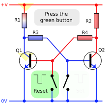
*Flip-flop (electronics) — placed from the Real G.E.N.E.R.A.T.I.V.E. course library (Electronics room). Source: Wikimedia Commons (via Wikipedia article media). [Details & license](https://commons.wikimedia.org/wiki/File:Transistor_Bistable_interactive_animated-en.svg).*
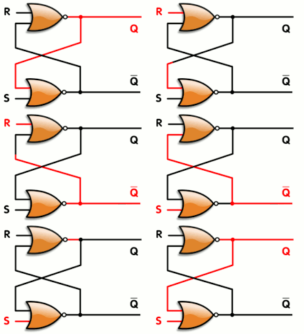
*Animated: Flip-flop (electronics) — placed from the Real G.E.N.E.R.A.T.I.V.E. course library (Electronics room). Source: Wikimedia Commons (via Wikipedia article media). [Details & license](https://commons.wikimedia.org/wiki/File:R-S_mk2.gif).*
> In electronics, flip-flops and latches are circuits that have two stable states that can store state information – a bistable multivibrator. The circuit can be made to change state by signals applied to one or more control inputs and will output its state (often along with its logical complement too). ([Wikipedia](https://en.wikipedia.org/wiki/Flip-flop_%28electronics%29))
<!-- REAL-GENERATIVE-MEDIA:END -->
<!-- SIGN-SYSTEMS:START -->
**Semiotic universals** (the notations and alphabet letters this article speaks — each opens its canonical card): state machine diagrams · clock time · wave · sampling · discretization. Index: the glyph gallery · SEMIOTICS PORTAL.
<!-- SIGN-SYSTEMS:END -->
## Media (PD/CC)
<!-- MEDIA-DEPLOY:Flip-flop_(electronics)/R-S_mk2.gif -->
!Gif Library/Logic gate/R-S mk2.gif
*R-S_mk2.gif · Napalm Llama · CC BY 2.0 · [source](https://commons.wikimedia.org/wiki/File:R-S_mk2.gif)*
<!-- /MEDIA-DEPLOY -->
*SPINTRONICS · branch **I — Integrated circuits** · MicroSim pattern **state machine / clocked-bistable** (pattern **N**) with a **signals-over-time timing diagram** (pattern **H**) — a flip-flop **block symbol** whose input pins and **Q / Q̄ output LEDs** light at logic 1, a **clock** you pulse one rising edge at a time, the selected type's **characteristic table** with the active row highlighted, and a scrolling **CLK / input / Q waveform** that records every edge. Draft staged by the headless draft queue; the publish stage adds frontmatter, the live editor iframe, and routes this into the Integrated-circuits branch folder. Slug `Flip-flop_(electronics)` is new to the registry (note: `new`).*
## Overview
A **flip-flop** is a circuit with two stable states that stores **one bit** of [[Information|information]] — the elementary unit of memory in digital [[Electronics|electronics]]. Left alone it *holds* its state indefinitely; on command it *changes* state. Because it remembers, it is the building block of every **sequential** circuit: registers, counters, shift registers, frequency dividers, and the state registers of the finite-state machines that run all digital hardware. A chip's memory and timing are, to first order, millions of flip-flops clocked in lock-step.
The first such circuit was the **Eccles–Jordan trigger circuit**, built from two cross-coupled vacuum tubes by the British physicists **William Eccles** and **F. W. Jordan**, who filed their patent ("Improvements in Ionic Relays") on 21 June 1918. The same topology — two inverting amplifiers wired in a positive-feedback loop — still sits at the heart of every modern flip-flop; only the active device changed, from triode to [[Transistor|transistor]] to a handful of CMOS gates. The onomatopoeic name "flip-flop" captures the snap between the two states.
A crucial distinction runs through the family. A **latch** is **level-sensitive**: while its enable (or clock) line is held active, its output tracks the inputs *transparently*. A **flip-flop** is **edge-triggered**: it samples its inputs only at the instant of a clock **transition** (conventionally the rising edge ↑) and ignores them the rest of the time. Edge-triggering is what lets thousands of flip-flops update together on one clock tick without racing through combinational logic — the foundation of synchronous design. This MicroSim models the **edge-triggered** flip-flop, in its four canonical types: **SR, D, JK,** and **T**.
## The physics / derivation
**Bistability from [[Positive_feedback|positive feedback]].** Cross-couple two inverting gates — two NOR gates (or two NAND gates) with each output feeding the other's input — and the pair has exactly two self-consistent states: `Q = 0, Q̄ = 1` and `Q = 1, Q̄ = 0`. Each state reinforces itself through the loop, so the circuit *latches*. The two extra NOR inputs become **S** (set) and **R** (reset); driving `S = 1` forces `Q → 1`, driving `R = 1` forces `Q → 0`, and `S = R = 0` *holds*. Asserting both at once (`S = R = 1`) drives **both** outputs to the same level and leaves the next state **indeterminate** when they release — the "forbidden" condition of the SR latch.
**Gating and edge-triggering.** AND the inputs with a **clock** line and the latch becomes *synchronous*: it only responds while the clock is asserted (a gated/transparent latch, still level-sensitive). Cascade two such stages in a **master–slave** pair, or use a dynamic edge-detector, and the cell becomes **edge-triggered** — the master samples on one clock phase and the slave commits on the edge, so the output changes **once per clock**, exactly at the transition. The four flip-flop types (SR, D, T, JK) and the equations below were first set out systematically by Montgomery Phister and described by P. L. Lindley around 1954.
**The four types — characteristic tables and equations.** A flip-flop's behavior is captured by its **characteristic equation**, which gives the next state `Q⁺` (the value after the next active edge) from the inputs and the present state `Q`:
```
SR (set / reset) Q+ = S + R'·Q subject to S·R = 0
S R | Q+
0 0 | Q (hold)
0 1 | 0 (reset)
1 0 | 1 (set)
1 1 | X (invalid / forbidden)
D (data / delay) Q+ = D
D | Q+
0 | 0
1 | 1 the output simply becomes the input, delayed one clock
JK (the universal type) Q+ = J·Q' + K'·Q
J K | Q+
0 0 | Q (hold)
0 1 | 0 (reset)
1 0 | 1 (set)
1 1 | Q' (toggle) JK replaces SR's forbidden state with a useful TOGGLE
T (toggle / trigger) Q+ = T (+) Q = T XOR Q
T | Q+
0 | Q (hold)
1 | Q' (toggle) a T flip-flop with T=1 divides the clock by 2 -> a counter bit
```
Here `'` denotes complement (NOT), `+` is OR, `·` is AND, and `(+)` is XOR. The **JK** flip-flop is the most general: it behaves like SR for the set/reset corners but, instead of an illegal `1 1` state, it **toggles** — which is why it can build counters directly. The **D** flip-flop is the workhorse of registers and pipelines (it just captures data each clock). The **T** flip-flop, obtained by tying `J = K = 1` or feeding back `Q̄` to D, **halves the clock frequency**, making it the natural cell of a ripple or synchronous counter. (Note the **excitation table** is the inverse view — "what inputs are needed to *cause* a given `Q → Q⁺`?" — and is what you use to *design* a counter; this sim shows the forward **characteristic** view.)
**Real-device limits.** An ideal flip-flop updates instantly, but a physical one imposes **timing constraints**: the input must be stable for a **setup time** `t_su` *before* the edge and a **hold time** `t_h` *after* it, and the output appears only after a **clock-to-Q propagation delay** `t_CO`. Violating setup/hold can drive the cell **metastable** — hovering between 0 and 1 for an unbounded time. Those parameters belong to device-level study; here the focus is the clean logical behavior and the edge-by-edge waveform.
## Parameter table (controls → real symbols)
| Control | Symbol | Meaning | Range (sim) |
|---------|:------:|---------|-------------|
| flip-flop type | — | which clocked bistable the symbol implements | {SR, D, JK, T} (index 0–3) |
| input 1 | `S` / `D` / `J` / `T` | the primary synchronous input (meaning set by the type) | {0, 1} |
| input 2 | `R` / — / `K` / — | the second input; present **only** for SR and JK | {0, 1} |
| clock | `CLK ↑` | apply one **rising edge**: sample the inputs and commit `Q⁺` | event (one edge per press) |
| reset | — | restore type=SR, all inputs 0, `Q = 0`, and clear the waveform | — |
*Derived and displayed:* the present output `Q` and its complement `Q̄` (drawn as LEDs), the **pending next state** `Q⁺ = f(inputs, Q)` that the *next* edge will commit, the type's ASCII **characteristic equation** (e.g. `Q+ = J*Q' + K'*Q` for JK), the highlighted **characteristic-table row** matching the live inputs, a one-line property note (e.g. *"JK 1,1 -> toggle: the type that builds counters"*, *"SR 1,1 -> forbidden: outputs indeterminate"*), and a rolling **timing diagram** of `CLK`, the input(s), and `Q` over the last several clocks. Because a flip-flop is **edge-triggered**, changing an input between edges updates only the *pending* `Q⁺` preview — `Q` itself does not move until you pulse the clock, which is the whole point the sim makes visible.
## Learning objective
Predict the **next state** `Q⁺` of each flip-flop type from its present inputs and current state, and explain **why edge-triggering matters** — that the inputs are sampled only at the clock transition, so a synchronous [[System|system]] updates all its bits at once. Stepping the type slider and pulsing the clock, the learner connects three representations that must always agree: the **block symbol** (input pins, the clock pin with its edge-triangle `▷`, and the `Q`/`Q̄` LEDs), the **characteristic table / equation** (with the live row lit and `Q⁺` shown), and the **timing diagram** (each rising edge sampling the inputs and stepping `Q`). The intended "aha" moments are seeing that **D** just delays its input by one clock, that **T** with `T = 1` divides the clock by two (a counter bit), and that **JK** turns SR's forbidden `1 1` corner into a useful **toggle** — the single change that makes JK the universal sequential element.
<!-- CRAFT-LINK:START g12 -->
*Built to the [[WT!P5_js_Microsim_Master_Class|p5.js Master Class]].*
<!-- CRAFT-LINK:END -->
## Wikipedia : Wikitube
**Strict pair:** [Wikipedia](https://en.wikipedia.org/wiki/Flip-flop_%28electronics%29) : [Wikitube](https://en.wikitube.io/wiki/Flip-flop_%28electronics%29)
## Previous hub tags
Tree parent: [[Feedback]].
Legacy hubs: none.
---
*Sources: 1 legacy note. Minted wave 1, 2026-07-30 (v1.6 order).*