# Logic gate
## Microsim
<iframe src="https://editor.p5js.org/sciencenibber/full/S9b-es6n-" width="100%" height="620" frameborder="0" sandbox="allow-scripts allow-same-origin"></iframe>
<img src="../SPINTRONICS Images/Logic_gate.png" alt="Logic_gate microsim">
*Live sketch: [open in the p5.js editor](https://editor.p5js.org/sciencenibber/sketches/S9b-es6n-). The poster image above is a placeholder pending an attended or server-side canvas capture.*
The canvas pairs a **gate schematic** (left) with its **truth table** (right) over a control band. A slider steps the **seven-gate catalog**; two buttons toggle inputs **A** and **B** (you can also click the input **LED nodes** directly), and **reset** restores every control. As you change inputs, the gate's input and output **wires light green at logic 1** (thick, with a flow chevron) or stay grey at `0`, the **output LED** shows the computed `Y`, and the **matching row of the truth table is highlighted** so the symbol and the table never disagree. Stepping the gate redraws the **distinctive shape** — the D-shaped AND, the shield-shaped OR, the inverter triangle, the salmon **output bubble** on the inverting gates (NOT/NAND/NOR/XNOR), and the extra concave **back-curve** on XOR/XNOR — together with the live **Boolean expression** and a one-line property note. The sketch is discrete and input-driven, so it uses `noLoop()` + `redraw()` with the static frame baked into an offscreen buffer (no animating loop for the editor's loop-protector to trip).
**Possible extensions (publish/refine):** show the **CMOS transistor [[Implementation|implementation]]** of the selected gate (e.g. NAND = two PMOS in parallel pull-up + two NMOS in series pull-down) so the universal gates' silicon cost is visible; widen to **3-input** gates (`2^3 = 8` rows); add a **NAND-only / NOR-only "build any gate"** mode that wires the chosen function from universal gates; or animate a **propagation-delay** pulse traveling input-to-output to introduce timing.
```js
// Logic_gate.js -- Wikitube MicroSim
// Hub: SPINTRONICS | Branch: I - Integrated circuits
// Pattern: state / discrete-logic (Boolean truth-table + distinctive-shape
// gate schematic whose input/output wires LIGHT UP with the live
// logic level). The sim is DISCRETE and input-driven -- nothing
// evolves in time -- so we use noLoop() + redraw() on input. That is
// the safest p5-editor pattern (no draw loop for the editor's
// loop-protector to false-trip; no heavy per-frame inner loops).
//
// CONCEPT
// A logic gate is an idealized device that implements one Boolean function:
// it takes one or two binary inputs (A, B in {0,1}) and emits a single
// binary output Y = f(A,B). The seven canonical gates are built from the
// three primitive operations of Boolean algebra -- AND (conjunction),
// OR (disjunction) and NOT (complement):
// AND Y = A * B (1 only when BOTH inputs are 1)
// OR Y = A + B (1 when AT LEAST ONE input is 1)
// NOT Y = !A (inverter; one input)
// NAND Y = !(A * B) (AND then invert) -- universal
// NOR Y = !(A + B) (OR then invert) -- universal
// XOR Y = A (+) B (1 iff inputs DIFFER; addition mod 2)
// XNOR Y = !(A (+) B) (1 iff inputs are the SAME)
// NAND and NOR are each "functionally complete": every Boolean function,
// and hence every digital circuit, can be built from NAND alone (or NOR
// alone). The truth table -- the 2^n-row enumeration of outputs over all
// input combinations -- fully defines the gate; this MicroSim draws that
// table beside the gate symbol and lights the row that matches the inputs
// you set, so the symbol, the wires and the table all agree at a glance.
//
// GOLDEN RULES honoured: one file, one ARTICLE; 720x520 + pixelDensity(2);
// layout derived from width/height (no magic coords in draw); controls carry
// the field's real symbols + meaningful ranges (gate index 0..6; A,B in
// {0,1}); reset restores ALL state; HUD watermark (title + URL + hints +
// live equation) drawn LAST; ASCII-only in strings (Unicode only in
// comments); noLoop()+redraw(); static scenery baked into an offscreen
// buffer so draw() is cheap and loop-free; p5.disableFriendlyErrors = true;
// no top-level name collides with a p5 global OR method (checked: none of
// ratio/split/scale/color/red/green/blue/map/mag/select/value/text/key are
// used as identifiers; no ALT/GRID).
const ARTICLE = "Logic_gate"; // single source of truth (HUD + save name)
// ---- gate catalog: name, ASCII Boolean expression, drawn base shape, output
// bubble (inverting), single-input (NOT), and the XOR back-curve flag ----
const GATES = [
{ name: "AND", expr: "Y = A * B", base: "AND", bubble: false, single: false, xb: false },
{ name: "OR", expr: "Y = A + B", base: "OR", bubble: false, single: false, xb: false },
{ name: "NOT", expr: "Y = !A", base: "NOT", bubble: true, single: true, xb: false },
{ name: "NAND", expr: "Y = !(A * B)", base: "AND", bubble: true, single: false, xb: false },
{ name: "NOR", expr: "Y = !(A + B)", base: "OR", bubble: true, single: false, xb: false },
{ name: "XOR", expr: "Y = A (+) B", base: "OR", bubble: false, single: false, xb: true },
{ name: "XNOR", expr: "Y = !(A (+) B)", base: "OR", bubble: true, single: false, xb: true }
];
// ---- controls ----
let gateSlider, btnA, btnB, resetButton;
// ---- state (the source of truth the controls write) ----
let inA = 0; // input A in {0,1}
let inB = 0; // input B in {0,1}
// ---- baked static buffer (divider, captions, table frame) ----
let scenery;
// ---- layout (all derived in setup; never hard-coded inside draw) ----
let gxL, gyC, gbw, gbh; // gate symbol: body-left x, vertical center, width, height
let inX, outX; // input-node x (left) and output-node x (right)
let ttX0, ttY0, ttX1, ttY1; // truth-table box
let divY; // drawing / control divider
let stX, stY; // state-readout block origin
// ---- live input/output node positions (set in draw; read by mousePressed) ----
let nodeAx, nodeAy, nodeBx, nodeBy, nodeYx, nodeYy;
let curSingle = false; // is the current gate single-input (NOT)?
// ---- palette (ASCII identifiers; none collide with p5 globals/methods) ----
let BG, INK, MUTE, FRAME, BODYC, EDGEC, HI, LO, HILITE, ACC, BUBBLEC;
function setup() {
createCanvas(720, 520);
pixelDensity(2);
p5.disableFriendlyErrors = true; // clean + cheap; skip FES overhead
textFont("monospace");
BG = color(14, 18, 32); // deep navy background
INK = color(232, 238, 248); // primary text
MUTE = color(122, 136, 160); // captions / secondary text
FRAME = color(58, 70, 94); // frames and divider
BODYC = color(38, 48, 72); // gate body fill
EDGEC = color(150, 165, 195); // gate outline
HI = color(60, 214, 130); // logic 1 (green): lit wires + LEDs
LO = color(96, 108, 132); // logic 0 (grey): dim wires + LEDs
HILITE = color(255, 224, 120); // active truth-table row (yellow)
ACC = color(120, 200, 255); // accents / gate name (cyan)
BUBBLEC = color(255, 150, 120); // inverting-output bubble (salmon)
// --- regions derived from the canvas, not magic numbers in draw ---
divY = 432;
gxL = 150; gyC = 200; gbw = 120; gbh = 96; // gate symbol box
inX = 74; outX = 372; // signal node columns
ttX0 = 470; ttY0 = 72; ttX1 = 690; ttY1 = 300; // truth-table box
stX = 40; stY = 300; // state readout origin
buildControls();
buildScenery(); // bake static art once -> draw() is cheap
noLoop(); // discrete sim: render only on input
}
function buildControls() {
// gate selector: one slider stepping the 7-gate catalog by integer index
gateSlider = createSlider(0, GATES.length - 1, 0, 1);
gateSlider.position(150, 446);
gateSlider.style("width", "210px");
gateSlider.input(redraw); // noLoop -> redraw on every change
// binary inputs are most natural as toggles, not 0..1 sliders
btnA = createButton("A = 0");
btnA.position(150, 478);
btnA.style("width", "78px");
btnA.mousePressed(toggleA);
btnB = createButton("B = 0");
btnB.position(236, 478);
btnB.style("width", "78px");
btnB.mousePressed(toggleB);
resetButton = createButton("reset");
resetButton.position(322, 478);
resetButton.style("width", "70px");
resetButton.mousePressed(resetAll);
}
function toggleA() { inA = inA ? 0 : 1; redraw(); } // flip bit A
function toggleB() {
// B is ignored for the single-input NOT gate
if (GATES[gateIndex()].single) return;
inB = inB ? 0 : 1;
redraw();
}
function resetAll() {
// reset restores ALL state, not just some
gateSlider.value(0);
inA = 0;
inB = 0;
redraw();
}
// ---- read the gate index once, clamped to the catalog ----
function gateIndex() {
return constrain(Math.round(gateSlider.value()), 0, GATES.length - 1);
}
// ---- the Boolean function itself: Y = f(A,B) for each gate ----
function computeOut(nm, a, b) {
switch (nm) {
case "AND": return (a && b) ? 1 : 0;
case "OR": return (a || b) ? 1 : 0;
case "NOT": return a ? 0 : 1;
case "NAND": return (a && b) ? 0 : 1;
case "NOR": return (a || b) ? 0 : 1;
case "XOR": return (a !== b) ? 1 : 0;
case "XNOR": return (a === b) ? 1 : 0;
}
return 0;
}
function draw() {
background(BG);
image(scenery, 0, 0); // blit baked static scenery
// read every control ONCE into named locals
const g = GATES[gateIndex()];
const a = inA;
const b = g.single ? 0 : inB; // NOT has no B
const y = computeOut(g.name, a, b);
curSingle = g.single;
refreshButtons(g); // keep button labels in sync (cheap)
drawGateName(g, a, b, y); // big gate label above the symbol
drawWires(g, a, b, y); // input/output leads, lit by logic level
drawGate(g); // distinctive-shape body + bubble (opaque)
drawNodes(g, a, b, y); // A,B input LEDs + Y output LED
drawTruth(g, a, b); // truth table with the active row lit
drawState(g, a, b, y); // headline evaluation + universality note
drawHUD(g, a, b, y); // HUD watermark, drawn LAST
}
// ====================================================================
// GATE SYMBOL
// ====================================================================
// big gate name centered above the body
function drawGateName(g, a, b, y) {
noStroke(); textAlign(CENTER, BOTTOM);
fill(ACC); textSize(20);
text(g.name, gxL + gbw / 2, gyC - gbh / 2 - 16);
fill(MUTE); textSize(11);
text(g.expr, gxL + gbw / 2, gyC - gbh / 2 - 2);
}
// input + output leads; a lead carries the logic level it transmits, so a
// HIGH wire is drawn thick + green with a small flow chevron, LOW is thin grey
function drawWires(g, a, b, y) {
const topY = gyC - gbh / 2;
const yA = g.single ? gyC : gyC - gbh * 0.23;
const yB = gyC + gbh * 0.23;
// wires run slightly INTO the body region; the opaque body is drawn on top
const xAttach = (g.base === "OR") ? gxL + 22 : gxL + 8;
const outStart = g.bubble ? gxL + gbw + 16 : gxL + gbw;
drawWire(inX, yA, xAttach, yA, a); // input A lead
if (!g.single) drawWire(inX, yB, xAttach, yB, b); // input B lead
drawWire(outStart, gyC, outX, gyC, y); // output Y lead
// stash node positions for click hit-testing
nodeAx = inX; nodeAy = yA;
nodeBx = inX; nodeBy = yB;
nodeYx = outX; nodeYy = gyC;
}
// one lead, colored by its logic level (1 = green/thick, 0 = grey/thin)
function drawWire(x0, yy0, x1, yy1, on) {
stroke(on ? HI : LO);
strokeWeight(on ? 3.2 : 1.8);
line(x0, yy0, x1, yy1);
if (on && x1 - x0 > 24) {
// small rightward flow chevron at the wire midpoint
const mx = (x0 + x1) / 2, my = (yy0 + yy1) / 2;
line(mx - 3, my - 4, mx + 4, my);
line(mx + 4, my, mx - 3, my + 4);
}
}
// the body of the gate in distinctive-shape (ANSI/IEC "distinctive") form
function drawGate(g) {
stroke(EDGEC); strokeWeight(2.2); fill(BODYC);
if (g.base === "AND") shapeAND(gxL, gyC, gbw, gbh);
else if (g.base === "OR") shapeOR(gxL, gyC, gbw, gbh);
else shapeNOT(gxL, gyC, gbw, gbh);
if (g.xb) shapeXORback(gxL, gyC, gbh); // XOR/XNOR extra back-curve
if (g.bubble) { // inverting-output bubble
const cx = (g.base === "NOT") ? gxL + gbw + 8 : gxL + gbw + 8;
noStroke(); fill(BUBBLEC); circle(cx, gyC, 14);
stroke(EDGEC); strokeWeight(1.6); noFill(); circle(cx, gyC, 14);
}
}
// D-shaped AND body: flat left + top/bottom, right semicircle
function shapeAND(xL, yC, bw, bh) {
const r = bh / 2;
const sx = xL + (bw - r); // center x of the right semicircle
beginShape();
vertex(xL, yC - bh / 2);
vertex(sx, yC - bh / 2);
arcVerts(sx, yC, r, -HALF_PI, HALF_PI, 26); // top -> right -> bottom
vertex(xL, yC + bh / 2);
endShape(CLOSE);
}
// shield-shaped OR body: convex top/bottom meeting at a tip, concave back
function shapeOR(xL, yC, bw, bh) {
const topY = yC - bh / 2, botY = yC + bh / 2, tipX = xL + bw;
beginShape();
vertex(xL, topY);
bezierVertex(xL + bw * 0.45, topY, xL + bw * 0.82, yC - bh * 0.20, tipX, yC);
bezierVertex(xL + bw * 0.82, yC + bh * 0.20, xL + bw * 0.45, botY, xL, botY);
bezierVertex(xL + bw * 0.20, yC + bh * 0.28, xL + bw * 0.20, yC - bh * 0.28, xL, topY);
endShape(CLOSE);
}
// triangle (inverter/buffer body); the bubble is added by the caller
function shapeNOT(xL, yC, bw, bh) {
beginShape();
vertex(xL, yC - bh / 2);
vertex(xL, yC + bh / 2);
vertex(xL + bw, yC);
endShape(CLOSE);
}
// the second concave arc behind an XOR/XNOR input side
function shapeXORback(xL, yC, bh) {
const topY = yC - bh / 2, botY = yC + bh / 2, off = 8;
push();
stroke(EDGEC); strokeWeight(2.2); noFill();
beginShape();
vertex(xL - off, topY);
bezierVertex(xL - off + 14, yC - bh * 0.28, xL - off + 14, yC + bh * 0.28, xL - off, botY);
endShape();
pop();
}
// build a circular arc as a vertex strip (runs once per redraw -> cheap)
function arcVerts(cx, cy, r, a0, a1, steps) {
for (let i = 0; i <= steps; i++) {
const ang = lerp(a0, a1, i / steps);
vertex(cx + r * cos(ang), cy + r * sin(ang));
}
}
// the three signal nodes drawn as LEDs (filled = 1/green, hollow = 0/grey)
function drawNodes(g, a, b, y) {
drawNode(nodeAx, nodeAy, a, "A");
if (!g.single) drawNode(nodeBx, nodeBy, b, "B");
drawNode(nodeYx, nodeYy, y, "Y");
}
function drawNode(x, yy, bit, lbl) {
const c = bit ? HI : LO;
stroke(c); strokeWeight(2); fill(bit ? c : BG);
circle(x, yy, 22);
noStroke(); fill(bit ? color(10, 20, 14) : INK); textSize(12); textAlign(CENTER, CENTER);
text(bit, x, yy + 1); // 0/1 inside the LED
fill(MUTE); textSize(12); textAlign(CENTER, BOTTOM);
text(lbl, x, yy - 14); // A / B / Y label above
}
// ====================================================================
// TRUTH TABLE
// ====================================================================
// enumerate every input combination and light the row matching (a,b)
function drawTruth(g, a, b) {
const rows = g.single
? [[0], [1]]
: [[0, 0], [0, 1], [1, 0], [1, 1]];
const cols = g.single ? ["A", "Y"] : ["A", "B", "Y"];
const nCol = cols.length;
const padTop = 30;
const rowH = (ttY1 - (ttY0 + padTop)) / rows.length;
const colW = (ttX1 - ttX0) / nCol;
// header
noStroke(); textAlign(CENTER, CENTER);
fill(INK); textSize(13);
for (let c = 0; c < nCol; c++) {
text(cols[c], ttX0 + colW * (c + 0.5), ttY0 + 15);
}
stroke(FRAME); strokeWeight(1);
line(ttX0, ttY0 + padTop, ttX1, ttY0 + padTop);
for (let rIdx = 0; rIdx < rows.length; rIdx++) {
const ra = rows[rIdx][0];
const rb = g.single ? 0 : rows[rIdx][1];
const ry = computeOut(g.name, ra, rb);
const y0 = ttY0 + padTop + rowH * rIdx;
// highlight the row that matches the live inputs
const match = g.single ? (ra === a) : (ra === a && rb === b);
if (match) {
noStroke(); fill(red(HILITE), green(HILITE), blue(HILITE), 46);
rect(ttX0, y0, ttX1 - ttX0, rowH);
stroke(HILITE); strokeWeight(1.4); noFill();
rect(ttX0 + 1, y0 + 1, ttX1 - ttX0 - 2, rowH - 2);
}
// cells: inputs in muted ink, the output Y colored by its value
textAlign(CENTER, CENTER); noStroke(); textSize(13);
const vals = g.single ? [ra, ry] : [ra, rb, ry];
for (let c = 0; c < nCol; c++) {
const isOut = (c === nCol - 1);
if (isOut) fill(vals[c] ? HI : LO);
else fill(match ? INK : MUTE);
text(vals[c], ttX0 + colW * (c + 0.5), y0 + rowH / 2);
}
}
// column separators
stroke(FRAME); strokeWeight(1);
for (let c = 1; c < nCol; c++) line(ttX0 + colW * c, ttY0 + padTop, ttX0 + colW * c, ttY1);
}
// ====================================================================
// STATE READOUT + HUD
// ====================================================================
// headline evaluation under the gate, plus a one-line property note
function drawState(g, a, b, y) {
noStroke(); textAlign(LEFT, TOP);
// current evaluation, big
let lhs;
if (g.single) lhs = "NOT " + a;
else lhs = a + " " + g.name + " " + b;
fill(INK); textSize(16);
text(lhs + " -> Y = " + y, stX, stY);
// colored verdict chip
fill(y ? HI : LO); textSize(13);
text(y ? "output HIGH (1)" : "output LOW (0)", stX, stY + 26);
// a short property note keyed to the gate (educational seasoning)
fill(MUTE); textSize(12);
text(gateNote(g.name), stX, stY + 50);
// n-input reminder
fill(MUTE); textSize(11);
const combos = g.single ? 2 : 4;
text("truth table: " + combos + " rows (2^" + (g.single ? 1 : 2) + " input combinations)",
stX, stY + 74);
}
// one-line characterisation of each gate (ASCII only)
function gateNote(nm) {
switch (nm) {
case "AND": return "AND: HIGH only when BOTH inputs are 1.";
case "OR": return "OR: HIGH when AT LEAST ONE input is 1.";
case "NOT": return "NOT (inverter): output is the complement of A.";
case "NAND": return "NAND: universal -- any logic is built from NAND alone.";
case "NOR": return "NOR: universal -- any logic is built from NOR alone.";
case "XOR": return "XOR: HIGH iff inputs DIFFER (addition mod 2).";
case "XNOR": return "XNOR: HIGH iff inputs are the SAME (equality).";
}
return "";
}
// HUD watermark: title, URL, control hints, live equation footer (drawn LAST)
function drawHUD(g, a, b, y) {
noStroke(); textAlign(LEFT, TOP);
fill(INK); textSize(15);
text("Logic gate -- set the inputs, watch the gate decide", 16, 12);
fill(MUTE); textSize(11);
text("en.wikitube.io/wiki/Logic_gate", 16, 33);
// control hints (above the divider, in the left label column)
fill(MUTE); textSize(11); textAlign(LEFT, BOTTOM);
text("gate: slider inputs: click A / B (or the LED nodes) reset", 18, divY - 6);
// left-column control labels in the control band
textAlign(LEFT, CENTER); fill(INK); textSize(12);
text("gate", 18, 454);
text("inputs", 18, 488);
// live equation footer (drawn last, bottom)
fill(MUTE); textSize(12); textAlign(LEFT, BOTTOM);
const lhs = g.single ? ("NOT " + a) : (a + " " + g.name + " " + b);
text(g.expr + " now: " + lhs + " = " + y, 16, height - 8);
}
// ---- baked static scenery (background, divider, captions, table frame) ----
function buildScenery() {
scenery = createGraphics(720, 520);
const sg = scenery;
sg.pixelDensity(2);
sg.background(BG);
sg.textFont("monospace");
// section captions
sg.noStroke(); sg.fill(MUTE); sg.textSize(11); sg.textAlign(LEFT, TOP);
sg.text("gate symbol + live signals (green = logic 1)", gxL - 78, 56);
sg.textAlign(CENTER, TOP);
sg.text("truth table", (ttX0 + ttX1) / 2, 56);
// truth-table outer frame
sg.stroke(FRAME); sg.strokeWeight(1.4); sg.noFill();
sg.rect(ttX0, ttY0, ttX1 - ttX0, ttY1 - ttY0);
// divider between the drawing region and the control region
sg.stroke(FRAME); sg.strokeWeight(1);
sg.line(16, divY, 704, divY);
}
// ---- canvas clicks on the input LED nodes toggle that bit (bonus control) ----
function mousePressed() {
// ignore clicks outside the canvas
if (mouseX < 0 || mouseX > width || mouseY < 0 || mouseY > height) return;
if (dist(mouseX, mouseY, nodeAx, nodeAy) <= 14) { toggleA(); return; }
if (!curSingle && dist(mouseX, mouseY, nodeBx, nodeBy) <= 14) { toggleB(); return; }
}
// keep the toggle-button captions in sync with state + gate arity
function refreshButtons(g) {
btnA.html("A = " + inA);
if (g.single) { btnB.html("B (n/a)"); }
else { btnB.html("B = " + inB); }
}
```
<!-- REAL-GENERATIVE-MEDIA:START -->
## Links (Wikipedia order)
<!-- injected from _registry/childlinks/Logic_gate.json (2026-07-30T02:09:12Z) -->
`AND-OR-invert` · `AND_gate` · `Akira_Nakashima` · `Allan_Marquand` · `Amplifier` · `Analytical_engine` · `And-inverter_graph` · `Application-specific_integrated_circuit` · `Arithmetic` · `Arithmetic_logic_unit` · `Asynchronous_circuit` · `BiCMOS` · [[Binary_number]] · `Boolean_algebra` · `Boolean_circuit` · `Boolean_function` · `Bulletin_of_the_American_Mathematical_Society` · `Bus_(computing)` · `CMOS` · `Cambridge_University_Press` · `Capacitance` · `Capacitor` · `Carry-lookahead_adder` · `Charles_Babbage` · `Charles_Sanders_Peirce` · `Charles_Sanders_Peirce_bibliography` · `Chih-Tang_Sah` · [[Claude_Shannon]] · `Clock_signal` · `Coincidence_circuit` · `Combinational_logic` · `Complex_programmable_logic_device` · `Computer` · `Computer_History_Museum` · [[Computer_architecture]] · [[Computer_hardware]] · `Computer_memory` · `Current-mode_logic` · `DNA` · `DNA_nanotechnology` · `De_Morgan's_laws` · `Defense_Logistics_Agency` · `Depletion-load_NMOS_logic` · `Digital_audio` · `Digital_cinematography` · `Digital_electronics` · `Digital_photography` · `Digital_radio` · `Digital_signal` · `Digital_signal_(signal_processing)` · [[Digital_signal_processing]] · `Digital_television` · `Digital_video` · `Diode` · `Diode_logic` · `Diode–transistor_logic` · `Direct-coupled_transistor_logic` · `Donald_Leo_Dietmeyer` · `Electronic_circuit` · `Electronic_component` · `Electronic_literature` · `Electronic_symbol` · `Emitter-coupled_logic` · `Espresso_heuristic_logic_minimizer` · `European_Committee_for_Standardization` · `Exclusive_or` · `Fairchild_Semiconductor` · `Fan-out` · `Field-effect_transistor` · `Field-programmable_gate_array` · `Field-programmable_object_array` · [[Finite-state_machine]] · [[Flip-flop_(electronics)]] · `Formal_equivalence_checking` · `Frank_Wanlass` · `Functional_completeness` · `Gain_(electronics)` · `Gate_array` · `Gate_equivalent` · `Generic_Array_Logic` · `Gottfried_Wilhelm_Leibniz` · `Hardware_acceleration` · `Hardware_description_language` · `Hardware_register` · `Harvard_Mark_I` · `Henry_M._Sheffer` · `High-level_synthesis` · `Hybrid_integrated_circuit` · [[I_Ching]] · `Inductor` · `Information_Processing_Society_of_Japan` · `Institute_of_Electrical_Engineers_of_Japan` · `Integrated_circuit` · `Integrated_injection_logic` · `John_Bardeen` · `Journal_of_the_American_Chemical_Society` · `Karnaugh_map` · `Konrad_Zuse` · [[Logic]] · `Logic_family` · `Logic_in_computer_science` · `Logic_level` · `Logic_redundancy` · `Logic_synthesis` · `Logical_NOR` · `Logical_conjunction` · `Ludwig_Wittgenstein` · `MAYA-II` · `MOSFET` · `Macrocell_array` · `Magnetic_logic` · `Material_conditional` · `Material_nonimplication` · `Mathematics` · `Memory_cell_(computing)` · `Metastability_(electronics)` · `Microprocessor` · `Mixed-signal_integrated_circuit` · `Molecular_logic_gate` · `Multiplexer` · `NAND_gate` · `NAND_logic` · `NEC` · `NMOS_logic` · `NOR_gate` · `NOR_logic` · `Nobel_Prize` · `OR-AND-invert` · `OR_gate` · `Optics` · `PMOS_logic` · `Parametron` · `Place_and_route` · `Placement_(electronic_design_automation)` · `Pneumatics` · `Printed_circuit_board` · `Printed_electronics` · `Processor_design` · `Processor_register` · `Programmable_Array_Logic` · `Programmable_logic_array` · `Programmable_logic_controller` · `Programmable_logic_device` · `Propagation_delay` · `Quantum_dot_cellular_automaton` · `Quantum_logic_gate` · `RCA_Corporation` · `Register-transfer_level` · `Relay` · `Relay_logic` · `Resistor` · `Resistor–transistor_logic` · `Reversible_computing` · `Rise_time` · `Routing_(electronic_design_automation)` · `Runt_pulse` · [[Semiconductor_device_fabrication]] · [[Sequential_logic]] · `Sheffer_stroke` · `Speed` · `Static_random-access_memory` · `Superconducting_computing` · `Switch` · `Switching_circuit_theory` · `Synchronous_circuit` · `Tampere_University_of_Technology` · `Telephony` · `Tensor_Processing_Unit` · `Texas_Instruments` · `Three-dimensional_integrated_circuit` · `Three-state_logic` · `Tractatus_Logico-Philosophicus` · `Transaction-level_modeling` · [[Transistor]] · `Transistor–transistor_logic` · `Truth_table` · `Two-element_Boolean_algebra` · `Unconventional_computing` · `United_States_Military_Standard` · `VHDL` · `Vacuum_tube` · `Verilog` · `Victor_Shestakov` · [[Voltage]] · `Walther_Bothe` · `World_War_II` · `XOR_gate` · `Yale_University_Press` · `Z1_(computer)`
## From the Real GENERATIVE library

*Logic gate — placed from the Real G.E.N.E.R.A.T.I.V.E. course library (Electronics room). Source: Wikimedia Commons (via Wikipedia article media). [Details & license](https://commons.wikimedia.org/wiki/File:Four_bit_adder_with_carry_lookahead.svg).*
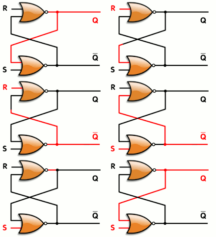
*Animated: Logic gate — placed from the Real G.E.N.E.R.A.T.I.V.E. course library (Electronics room). Source: Wikimedia Commons (via Wikipedia article media). [Details & license](https://commons.wikimedia.org/wiki/File:R-S_mk2.gif).*
> A logic gate is a device that performs a Boolean function, a logical operation performed on one or more binary inputs that produces a single binary output. Depending on the context, the term may refer to an ideal logic gate, one that has, for instance, zero rise time and unlimited fan-out, or it may refer to a non-ideal physical device[1] (see ideal and real ([Wikipedia](https://en.wikipedia.org/wiki/Logic_gate))
<!-- REAL-GENERATIVE-MEDIA:END -->
<!-- SIGN-SYSTEMS:START -->
**Semiotic universals** (the notations and alphabet letters this article speaks — each opens its canonical card): logic notation · logic gate symbols · circuit symbols iec · discretization · flow. Index: the glyph gallery · SEMIOTICS PORTAL.
<!-- SIGN-SYSTEMS:END -->
## Media (PD/CC)
<!-- MEDIA-DEPLOY:Logic_gate/R-S_mk2.gif -->
!Gif Library/Logic gate/R-S mk2.gif
*R-S_mk2.gif · Napalm Llama · CC BY 2.0 · [source](https://commons.wikimedia.org/wiki/File:R-S_mk2.gif)*
<!-- /MEDIA-DEPLOY -->
*Wikitube MicroSim -- SPINTRONICS hub, branch **I -- Integrated circuits** (Top 10). Source: [Logic gate -- Wikipedia](https://en.wikipedia.org/wiki/Logic_gate). MicroSim pattern: state / discrete-logic -- the seven canonical gates (AND, OR, NOT, NAND, NOR, XOR, XNOR) drawn in their distinctive shapes, with toggleable inputs A/B and a live-highlighted truth table.*
**Live sim:** en.wikitube.io/wiki/Logic_gate
---
## Overview
A **logic gate** is an idealized device that implements a **Boolean function**: it takes one or more **binary** inputs — each a logic `0` (low) or `1` (high) — and produces a single binary output. Gates are the atoms of digital [[Electronics|electronics]]. Wire them together and you build the adders, multiplexers, flip-flops, registers, arithmetic-logic units and ultimately the Microprocessor that runs every digital machine; a modern chip is, to first order, billions of a few gate types repeated and interconnected.
Physically a gate is realized with [[Transistor|transistors]] — most often complementary **CMOS** pairs, historically also bipolar **TTL**, and before that diodes and relays — but its *behavior* is captured completely by a small truth table, independent of how it is built. This MicroSim treats the gate at that behavioral level: the **seven canonical gates** — **AND, OR, NOT, NAND, NOR, XOR, XNOR** — drawn in their standard distinctive shapes, with the inputs you can toggle and the output the gate computes.
Two of the seven are special: **NAND** and **NOR** are each **functionally complete** (*universal*) — any Boolean function whatsoever, and therefore any digital circuit, can be assembled from copies of NAND alone, or of NOR alone. That is why a single gate type can tile an entire chip.
## The physics / derivation
**Boolean algebra.** Logic gates are the circuit embodiment of the two-valued algebra introduced by **[[George_Boole|George Boole]]** and applied to switching circuits by **[[Claude_Shannon|Claude Shannon]]**. The carrier set is `{0, 1}` and there are three primitive operations:
```
AND (conjunction) A * B : 1 only when A=1 AND B=1
OR (disjunction) A + B : 1 when A=1 OR B=1 (inclusive)
NOT (complement) !A : 1 becomes 0, 0 becomes 1
```
The remaining four gates are compositions of these:
```
NAND Y = !(A * B) AND followed by NOT
NOR Y = !(A + B) OR followed by NOT
XOR Y = A (+) B = (A * !B) + (!A * B) : 1 iff the inputs DIFFER
XNOR Y = !(A (+) B) : 1 iff the inputs are the SAME
```
**The truth table is the definition.** A gate with `n` inputs has exactly `2^n` possible input combinations, so its behavior is pinned down by a table of `2^n` rows. For the two-input gates that is four rows (`00, 01, 10, 11`); for the single-input inverter, two rows. Reading a gate *is* reading its table:
```
A B | AND OR NAND NOR XOR XNOR A | NOT
0 0 | 0 0 1 1 0 1 0 | 1
0 1 | 0 1 1 0 1 0 1 | 0
1 0 | 0 1 1 0 1 0
1 1 | 1 1 0 0 0 1
```
**De Morgan's laws** tie the inverting gates together and are the workhorse of gate-level algebra:
```
!(A * B) = !A + !B (NAND = OR of complemented inputs)
!(A + B) = !A * !B (NOR = AND of complemented inputs)
```
**Functional completeness.** Because `{AND, OR, NOT}` can express every Boolean function, and because NAND can reproduce all three — `NOT A = A NAND A`, `A AND B = NOT(A NAND B)`, `A OR B = (NOT A) NAND (NOT B)` — **NAND is universal**; the dual argument makes **NOR universal**. **XOR** deserves a special note: it is **addition modulo 2**, the bit-level carry-less sum that sits at the heart of binary adders, parity checks and stream ciphers.
**Real devices add cost.** Beyond the ideal table, a physical gate has a **propagation delay** (inputs take time to reach the output), a **fan-out** limit (how many gate inputs one output can drive), and **noise margins** (how far a real [[Voltage|voltage]] may stray from the ideal `0`/`1` rails and still be read correctly). Those parameters belong to the device-level sims ([[Transistor]], MOS transistor, CMOS); here the focus is the clean Boolean behavior.
## Parameter table (controls -> real symbols)
| Control | Symbol | Meaning | Range (sim) |
|---------|:------:|---------|-------------|
| gate type | `f` | which Boolean function the symbol implements; steps the 7-gate catalog | {AND, OR, NOT, NAND, NOR, XOR, XNOR} (index 0–6) |
| input A | `A` | first binary input (logic low / high) | {0, 1} |
| input B | `B` | second binary input; **ignored** for the single-input NOT | {0, 1} |
*Derived and displayed:* the output `Y = f(A, B)` (shown as a lit LED and as the highlighted truth-table row), the gate's ASCII **Boolean expression** (e.g. `Y = !(A * B)` for NAND), the number of input combinations `2^n`, and a one-line property note (e.g. *"NAND: universal — any logic is built from NAND alone"*, *"XOR: HIGH iff inputs differ — addition mod 2"*). The gate symbol's input and output **leads are colored by the logic level they carry** — green and thick for `1`, grey and thin for `0` — with a small flow chevron on each high wire, so the schematic, the LEDs and the truth-table row always agree.
## Learning objective
Read a logic gate as the realization of a Boolean function and **predict its output from its inputs** for all seven canonical gates. Toggling `A` and `B` and stepping through the catalog, the learner connects three representations that must agree: the **distinctive-shape symbol** (D-body AND, shield OR, triangle-plus-bubble inverter, the output bubble that marks an *inverting* gate, the extra back-curve that marks XOR/XNOR), the **Boolean expression**, and the **truth table** with its `2^n` rows. The intended "aha" is seeing that NAND is exactly AND with the output bubble (its column is the complement of AND's), that NOR is the bubbled OR, and that NAND/NOR are **universal** — the reason a single repeated gate can build an entire processor — while XOR's "1 iff different" column is the carry-less binary sum.
<!-- CRAFT-LINK:START g12 -->
*Built to the [[WT!P5_js_Microsim_Master_Class|p5.js Master Class]].*
<!-- CRAFT-LINK:END -->
<!-- SPINEPATH:BEGIN g20 — shortest chain of Wikipedia links between local articles to a Compendium Main article; do not hand-edit inside -->
*Connected to the Apex Spine:* Logic gate → [[Voltage|Voltage]] → [[Electrolysis_of_water|Electrolysis of water]] — [[WT!Thury_Hydrodynamics_Compendium|Compendium]] section 10, *Electrolysis: the canon in reverse*.
<!-- SPINEPATH:END -->
## Wikipedia : Wikitube
**Strict pair:** [Wikipedia](https://en.wikipedia.org/wiki/Logic_gate) : [Wikitube](https://en.wikitube.io/wiki/Logic_gate)
## Previous hub tags
Tree parents: [[Fault_tree_analysis]] · [[Feedback]].
Legacy hubs: none.
---
*Sources: 1 legacy note. Minted wave 1, 2026-07-30 (v1.6 order).*